Modular Wet Processing Technology at CFG-Chu Lai Float Glass JSC, Vietnam CAPACITY 2×100 tph PRODUCT YIELD
Capacity 2×100 tph
Product Yield ~71%
Water Recycled ~95%
Fe₂O₃ Achieved <0.05%
This paper presents the design rationale, process flowsheet development, and operational performance of a modular wet processing plant for the beneficiation of silica sand to float glass-grade specifications. The installation at CFG-Chu Lai Float Glass Joint Stock Company in central Vietnam processes raw sand ore characterised by elevated iron oxide content (~0.5% Fe₂O₃) and suboptimal silica purity (~98.5% SiO₂). Through a combination of attrition scrubbing (Atropure®), hydrocyclone classification (Centrimax®), spiral gravity concentration (Spiropure®), and upward-flow hydraulic classification (Vertimax®), the plant consistently produces a final product exceeding 99.3% SiO₂ with Fe₂O₃ reduced to below 0.05%, at a product yield of approximately 71% and water recovery of approximately 95%. The paper discusses laboratory and pilot-scale test work, full-scale plant configuration, metallurgical performance against variable feed conditions, and the environmental advantages of a gravity-based, chemical-free process circuit.
The global demand for high-quality flat glass continues to accelerate, driven by the growth of steel-and-glass construction, automotive glazing, and solar panel manufacturing. Vietnam, with extensive silica sand reserves concentrated in its central and northern provinces, is strategically positioned to serve both domestic consumption and regional export markets. However, exploiting these reserves for glass-grade applications requires addressing persistent quality challenges in the raw ore, principally elevated iron contamination and inconsistent granulometry.
CFG-Chu Lai Float Glass Joint Stock Company, established in 2006 within the Bac Chu Lai Industrial Park in Quang Nam Province, central Vietnam, is one of the country’s most significant glass manufacturing enterprises. Backed by a total investment of approximately USD 100 million, the company operates an integrated facility encompassing captive silica sand mines, a dedicated beneficiation plant, and a float glass line rated at 900 tonnes per day - approximately 30% of which is exported. The company employs around 150 personnel and reported a 17.9% year-on-year increase in net sales revenue in 2023.
1.1 CFlo’s Global Experience in Silica and Industrial Sand Processing
CFlo has developed deep expertise in silica sand purification and industrial sand processing over nearly two decades, having designed and commissioned beneficiation plants for some of the most demanding applications in the glass, foundry, solar, oil and gas, and ceramics sectors.The company’s Micrograder platform - its dedicated wet processing system for critical mineral recovery - employs a combination of attrition scrubbing, gravity concentration, magnetic separation, and hydraulic classification technologies, custom-configured for each project based on extensive laboratory and pilot-scale test work.
Notable silica sand installations include float glass-grade sand processing for Saint-Gobain in India and float glass sand beneficiation for Ghani Glass in Pakistan, alongside numerous other industrial silica projects across South and Southeast Asia, the Middle East, and Oceania. These projects span feed materials ranging from hard-rock silica to alluvial deposits, lignite overburden, and offshore dredged sand, demonstrating the adaptability of CFlo’s modular technology to diverse geological and commercial contexts.
With over 500 installations across 18 countries and an in-house DSIR approved Material Testing Services (MTS) laboratory that has analysed thousands of samples over 19 years, CFlo brings unmatched process knowledge to every silica sand project. The Chu Lai installation described in this paper represents one of the largest and most technically demanding glass sand beneficiation plants in CFlo’s portfolio.
The silica sand ore is sourced from captive open-pit mines proximate to the Chu Lai facility. Mineralogical and chemical characterisation of representative samples revealed the following constraints for float glass feedstock production:
Table 1: Raw Ore Characteristics vs. Float Glass Specifications
| Parameter | Raw Ore (Typical) | Float Glass Requirement |
| SiO₂ | ~98.5% | >99.0% |
| Fe₂O₃ | ~0.50% | <0.05% |
| Al₂O₃ | 0.4–0.8% (variable) | <0.5% |
| TiO₂ | Present (trace) | Minimal |
| +700 μm fraction | Present | Zero |
| +600 μm fraction | Significant | <1% |
| Target product range | Broad PSD | 150–600 μm |
The ten-fold reduction in iron oxide content required (from ~0.50% to <0.05%) represents a substantial metallurgical challenge. Iron in the Chu Lai ore occurs both as surface-adhering contamination amenable to attrition scrubbing, and as discrete heavy mineral grains requiring gravity-based separation. The variable nature of the ore between mine faces - with fluctuations in both chemical grade and particle size distribution - further demands a process circuit with inherent flexibility.
3.1 Bench-Scale Test Programme
CFlo’s Material Testing Services (MTS) laboratory in Kolkata, India, conducted an extensive test programme on multiple representative ore samples. The core equipment utilised included wet sieve shakers, hydrocyclone test rigs, attrition cells, spiral gravity concentrators, and counter-flow classifiers. The primary objectives were: (i) to determine the proportion of iron existing as surface contamination versus liberated heavy mineral grains; (ii) to establish the optimal attrition energy input for iron liberation; and (iii) to develop a gravity separation flowsheet capable of achieving <0.05% Fe₂O₃ in the product.
Initial washing and sizing between 600 and 150 microns confirmed that a significant fraction of the iron was surface-adhering and removable by hydraulic washing alone. Subsequent attrition scrubbing trials at varying energy inputs demonstrated that the remaining bound iron could be effectively liberated, converting it to a form amenable to density-based separation.
3.2 Pilot-Scale Validation
To overcome the limitations inherent in bench-scale testing (sample masses of approximately 1 kg), CFlo conducted pilot-scale trials on approximately one tonne of ore utilising its proprietary Screenmax® precision fine screening technology and Spiropure® spiral concentrators. The pilot programme confirmed the viability of the proposed flowsheet at throughputs representative of industrial operation, with product quality consistently meeting float glass specifications across multiple trial runs.
The laboratory and pilot-scale work is the foundation of every CFlo project. We do not extrapolate from assumptions - we validate the process at meaningful scale before committing to a plant design. For Chu Lai, our test programme confirmed that we could consistently achieve float glass-grade product from a variable and challenging feed.”
Micrograder F70D Configuration
Based on the validated pilot flowsheet, a Micrograder F70D plant was designed with an initial throughput capacity of 70 tph each, subsequently expanded to a 2×100 tph dual-line configuration. The Micrograder is CFlo’s modular wet processing platform for critical mineral recovery and silica beneficiation applications. It is factory-assembled at CFlo’s manufacturing facilities in Kolkata, shipped internationally in standard 40-foot containers, and erected on site with minimal civil works - typically requiring only a prepared concrete pad and utility connections.
The plant footprint of each line is approximately 42 m × 48.5 m with a maximum elevation of 18 m, as illustrated in the general arrangement drawing (Figure 2). The connected electrical load is approximately 375 kW at 415 V / 50 Hz / 3-phase, with a fresh water make-up requirement of 25–30 m³/hr.
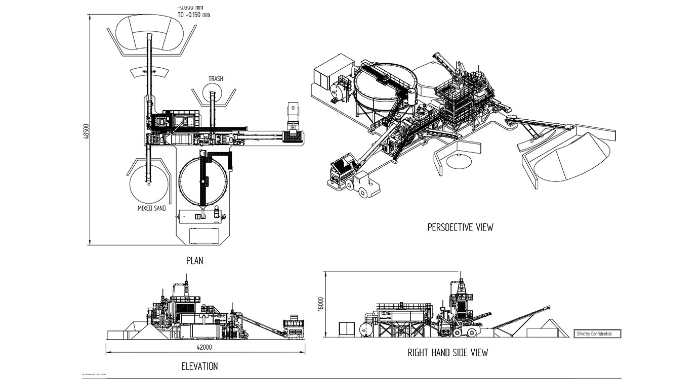
Figure 2: Micrograder F70D General Arrangement - Plan (top left), Perspective (top right), Elevation (bottom left), Right-Hand Side View (bottom right). Product size range: -0.600 to +0.150 mm.
Table 2: Plant Design Parameters for each line
| Parameter | Parameter Value |
| Design Throughput | 2 × 100 tph (expanded from initial 70 tph each) |
| Plant Footprint | 42 m × 48.5 m |
| Maximum Elevation | 18 m |
| Connected Electrical Load | ~375 kW (415 V, 50 Hz, 3-phase) |
| Fresh Water Make-up | 25–30 m³/hr |
| Feed Size (design) | -0.600 mm to +0.150 mm |
| Target Product | Glass-grade SiO₂ >99%, Fe₂O₃ <0.05% |
| Water Recovery (design) | ≥95% |
| Automation | PLC with colour touchscreen HMI, remote access |
| Shipping Configuration | Standard 40-foot containers (modular) |
The Micrograder F70D employs an eight-stage wet processing circuit. Each stage is described below with reference to the unit operations and proprietary CFlo equipment deployed.
Stage 1: Feed System (Feedmax®)
Raw sand ore is delivered to a Feedmax® feed hopper fitted with a scalping grizzly at 80 mm aperture to reject deleterious oversize material. A variable-speed drive (VSD) belt feeder meters the ore onto a Carrymax® feed conveyor equipped with an in-line belt weigher, enabling continuous monitoring and real-time adjustment of the volumetric feed rate. This arrangement ensures stable, controlled throughput to the downstream washing circuit regardless of the variability in loader feed patterns.
Stage 2: Primary Washing and Attrition Scrubbing (Atropure®)
The feed enters a Screenmax® wet sizing screen which separates trash and oversize material (>5 mm) from the processable sand fraction. The minus 5 mm material is deslimed and routed to a pair of heavy-duty Atropure® attrition scrubbers. The Atropure® operates on the principle of high-intensity inter-particle abrasion: the paddles, arranged in a fan configuration, generate intense shear forces that dislodge surface-bound iron oxides, clay minerals, and other contaminants from individual sand grains without fracturing the silica particles themselves. The cast chrome paddle construction ensures extended service life under abrasive conditions. The scrubbed slurry is then directed to an integrated fines washing system comprising sumps with heavy-duty slurry pumps, Screenmax® rinsing screens, and two-stage Centrimax® hydrocyclone classification.
Stage 3: Secondary Sizing and Product Recovery
Following attrition, the sand slurry is pumped to a Screenmax® precision sizing screen configured for an accurate 600-micron cut. The oversize fraction (+600 μm) is dewatered on a dedicated Screenmax® dewatering screen and transferred via Carrymax® wing stockpile conveyors to a separate bay for sale as a construction-grade by-product. This secondary product stream represents an additional revenue source, improving overall project economics. The undersize fraction (-600 μm) proceeds to gravity separation.
Stage 4: Gravity Separation (Spiropure® and Centrimax®)
The minus 600-micron sand slurry is pumped to Centrimax® hydrocyclones for pre-concentration, followed by treatment on Spiropure® spiral gravity concentrators. The Spiropure® exploits the specific gravity differential between silica (SG ~2.65) and iron-bearing heavy minerals such as ilmenite, magnetite, and hematite (SG 4.5–5.2). As slurry descends the helical trough, centrifugal and gravitational forces cause the denser iron minerals to migrate to the inner channel where they are collected and rejected as a concentrate stream. This concentrate is blended with the secondary construction sand product. The Spiropure® operates entirely by gravity with no reagent inputs, eliminating chemical costs and environmental discharge concerns.
Stage 5: Hydraulic Classification (Vertimax®)
The gravity-separated product undergoes final polishing in the Vertimax® upward-flow classifier. The Vertimax® operates on the principle of hindered settling in a counter-current water column. Feed slurry enters the classifier as the underflow of a Centrimax® hydrocyclone, while clean water is introduced through evenly distributed spray nozzles at the base of the tank, creating a precisely controlled ascending current.
Particles whose settling velocity exceeds the upward water velocity sink to the base of the classifier and are discharged through a pneumatically actuated, electronically controlled pinch valve. Finer, lighter particles whose drag exceeds their settling tendency are carried over a peripheral weir at the top of the classifier and report to the tailings circuit. The open/close timing of the pinch valve is the primary control variable, allowing operators to fine-tune the product cut point in real time. A pressure transducer mounted near the base provides continuous measurement of the bed density, which is displayed on the PLC as a percentage reading against a target setpoint, enabling automated regulation of the discharge regime.
This stage is critical for achieving the stringent particle size specification of -600 +150 μm with the +600 μm fraction at less than 1% and +700 μm at zero. The Vertimax® product is dewatered on a Screenmax® dewatering screen, producing a final stockpiled product at approximately 15% moisture.
Stage 6: Water Recovery (Hydromax® WRS)
The combined overflow streams from all hydrocyclone and classification stages are routed to a Hydromax® Water Recycling System - a high-rate thickener featuring a four-arm rake system with angled scrapers, a direct-drive motor and gearbox, and a peripheral weir for clean water discharge. Incoming dirty water is mixed with flocculant in a de-aeration chamber before entering the main tank, where suspended solids bind to the polymer and settle to the base. The rotating rakes condition the sludge bed, preventing compaction, while clean overflow water is continuously discharged via the peripheral weir to the Hydrostore® water storage and pumping system for immediate recirculation.
The Hydromax® recovers a significant proportion of process water at the primary thickening stage, with underflow sludge discharged at a density of circa 450–550 g/litre via a heavy-duty centrifugal sludge pump. Polyelectrolyte consumption is exceptionally low - typically five to seven times less than conventional thickening systems - owing to the minimal agitation of the sludge bed and efficient flocculant dosing via the integrated Polydex® polymer dosing station. The Hydromax® is constructed from mild steel bolted sections, allowing rapid on-site assembly, and is fitted with pneumatic and electrically operated valves, automatic flushing, and a scraper support bridge with full walkway access for maintenance. Working in conjunction with the downstream EasySettle® sludge management system, which recovers additional water from the thickened sludge in the settlement pond, the combined Hydromax®-Easysettle® circuit achieves an overall water recovery of approximately 95%.
Stages 7 & 8: Sludge Management (Easysettle®)
Thickened sludge is pumped via flexible high-pressure feed pipe to a sludge disposal pond located within 100 m of the plant. The Polydex® polymer dosing station prepares a flocculant solution using a screw-feeder, mixing tank with twin propellers and ultrasonic sensor, and a dosing pump with in-line dilution and variable-speed gearboxes. An in-line mixer assembly on the slurry pipeline ensures thorough polymer-sludge contact prior to discharge. The EasySettle® system is fully PLC-controlled, with rotameter-based flow monitoring and automatic dosing adjustment. As the polymer-conditioned sludge settles in the pond, water is released and can be reclaimed via submersible pump for reuse, further closing the water loop.
A key measure of any beneficiation process is its robustness against feed variability. During sustained operation at Chu Lai, the plant feed deviated materially from the samples used in the original test programme - exhibiting lower SiO₂ content, elevated Al₂O₃, and a coarser particle size distribution. Despite these departures, the plant consistently met or exceeded target specifications, as summarised in Table 4.
| Parameter | Feed (Operational) | Product (Final) |
| SiO₂ | ~98.5% (lower than test work) | >99.3% |
| Fe₂O₃ | ~0.50% | <0.05% |
| Al₂O₃ | Higher than test work | Within glass spec |
| Particle Size Distribution | Coarser than test work | -600 +150 μm (spec met) |
| Product Yield | - | ~71% |
| Water Recovery | - | ~95% |
| Product Moisture | - | ~15% |
The close correlation between pilot-scale predictions and full-scale operational results - despite the changed feed characteristics - validates the robustness of the Micrograder process design and the flexibility inherent in the multi-stage circuit. The ability of the Vertimax® classifier to accommodate varying particle size distributions through real-time pinch valve adjustment proved particularly valuable in maintaining product specifications during periods of feed variability.
From an environmental perspective, the entirely gravity-based separation circuit eliminates the use of chemical reagents such as acids or organic collectors. This not only avoids the cost and complexity of reagent handling and effluent treatment but also ensures compliance with Vietnam’s increasingly stringent environmental discharge regulations. The near-closed-loop water circuit, with 95% overall recovery achieved through the combined operation of the Hydromax® WRS and Easysettle® sludge management system, minimises freshwater abstraction - an important consideration in regions where water resources are shared with agriculture and domestic users.
What distinguishes CFlo’s approach is the ability to deliver consistent product quality even when the feed changes - and in mining, feed variability is not the exception but the norm. At Chu Lai, the Micrograder platform demonstrated that gravity-based, chemical-free processing can meet the most demanding specifications in the float glass industry, while maintaining low operating costs and near-zero environmental discharge.
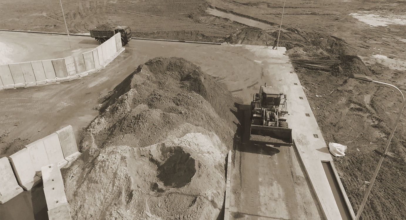
Figure 5: Raw sand ore receiving area showing wheel loader feeding the Feedmax® hopper. The laterite-rich overburden (red earth) visible in the background illustrates the geological context of the surrounding area.
Table 4: Process Equipment Schedule
| Equipment | Function | Technical Notes |
| Feedmax® | Scalping, Feeding & metering | 80 mm grizzly, VSD belt feeder, belt weigher |
| Carrymax® | Material transfer & stockpiling | Feed, wing, and mobile stockpile conveyors |
| Screenmax® | Sizing, rinsing & dewatering | Precision screening, Circular motion screens, Dewatering; all using polyurethane mats |
| Atropure® | Attrition scrubbing | Fan-arranged cast chrome paddles; high-shear |
| Centrimax® | Hydrocyclone separation | Xtril-lined; two-stage classification |
| Spiropure® | Spiral gravity concentration | SG-based heavy mineral rejection; no reagents |
| Vertimax® | Upward-flow hydraulic classification | Pinch valve control; pressure transducer bed measurement |
| Hydromax® | Water recycling (thickener) | Primary water recovery; 450–550 g/L sludge |
| Hydrostore® | Water storage & pumping | Recirculation to process circuit |
| EasySettle® | Sludge management | Polydex® dosing; PLC-controlled; combined ~95% water recovery with Hydromax® |
| PLC System | Plant automation | Colour touchscreen HMI; remote access capable |
The Chu Lai installation demonstrates the technical and economic viability of modular wet processing technology for producing float glass-grade silica sand from low-grade, variable-quality ore deposits. The key findings from this project are:
The project validates the application of CFlo’s Micrograder platform for high-purity silica sand beneficiation and provides a replicable model for glass sand operations throughout Southeast Asia and other regions where ore quality challenges constrain the domestic production of float glass-grade feedstock.
About Us
CFlo World Limited is the global leader in modular wet processing technology, operating across five regions - Asia, Middle East, UK & Europe, North America and Oceania. Our purpose is conserving resources and creating waste-free cities. With nearly two decades of innovation, over 500 installations across 18 countries and a growing portfolio of global patents, CFlo delivers bespoke equipment solutions for waste recycling, upcycling mining waste, ore beneficiation and critical mineral recovery. Powered by a world-class manufacturing and R&D centre and regional sales and service hubs with dedicated local teams, CFlo drives sustainable alternatives to natural sand by transforming construction & demolition waste (C&D) and mining waste into engineered sand and other building materials for the circular economy, while enhancing the value of mined ores and critical minerals for high-tech industries such as EV batteries. Through its B2B platform Doctor Sand, CFlo is organising the sand supply chain. The group mission is to help 100 countries replace natural sand with sustainable alternatives.
